RELAYS AND TEMPERATURE VARIATIONS
Most relay parameters are specified as maximum values over the rated temperature range of the specific relay. Users often find that key parameters differ significantly at ambient temperature (20-25°C) and sometimes fall into the trap of specifying their system around these ambient parameters. Additionally the actual temperature experienced by the relay can be far in excess of existing ambient temperatures due to the heat generated by the coil current and the contact load. Figure 1 is the summary of temperature effects on relay electrical characteristics.
The following formulas are sometimes useful in calculating the effects shown above.
1. Change in coil resistance due to change of ambient temperature can be calculated by the following formula.
R = R20 [1 + .0039 (T-20)]
Where: R = Coil resistance at given temperature
R20 = Coil resistance at 20°C
T = °C Ambient temperature
“Rule of Thumb” : For each 10°C change of temperature, coil resistance will change approximately 4%.
2. High and low temperature pick up voltage:
E2 = E1K2,
Where: E2 = Pick Up Voltage at T2 temperature
E1 = Pick Up Voltage at 20°C
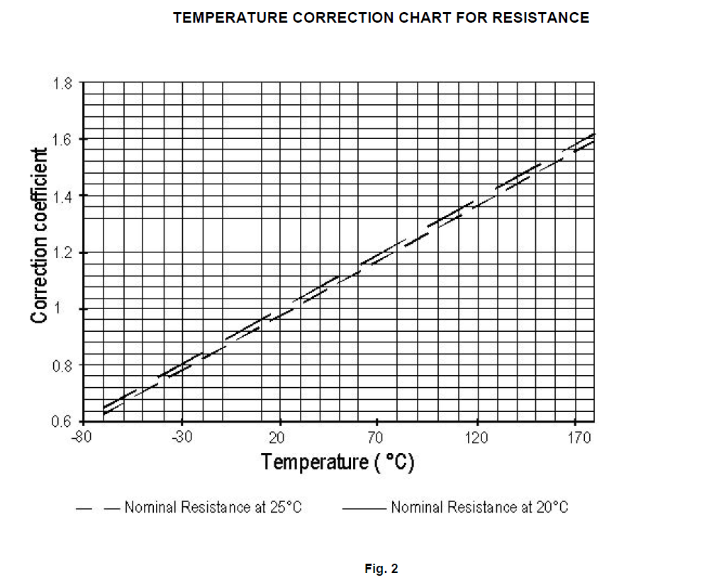
K2 = Coefficient of correction found on the graph in Fig. 2 at T2
3. Calculation of coil temperature rise when R initial and R final are known:
Delta T = (234.5 + T1) (R2/R1 – 1)
Delta T = Temperature rise (°C)
T1 = Initial temperature (°C)
R1 = Initial resistance (Ohms)
R2 = Final resistance (Ohms)
R2 = K2R1
Temperature can also be found by making the R2/R1 ratio = the
coefficient of correction graph in Fig. 2, and then finding the corresponding temperature.
EXAMPLE:
Catalog indicates coil resistance of 290 ohm at 25°C. What is the value at 125°C?
From the chart: 290 x 1.39 = 403.31 Ohms.


