Frequently Asked Questions
What does -300 at the end of the part number mean?
Leach assigns -300 as a military dash number designation for MIL-PRF-83536. It indicates a standard mil part with established reliability and circuit breaker capability.
-300 could be applied to both suppressed and non-suppressed coils.
For more details on Designator Dash #, please refer to our Relay numbering Guide
What are the different failure rates Leach offers?
For most of COTS relays, the failure rate is 5.0%/10,000 operations.
QPL parts have a designated failure rate at the end of their part number:
• L – 3.0%/10,000 operations
• M – 1.0%/10,000 operations
*For specific parts and environments, please contact Leach for the exact failure rate.
For a latching relay, how long does the coil need to be energized for the contacts to switch position?
For a latching relay, power needs to be provided for 100 milliseconds to ensure the contact switches. After that, if the power is removed, the contacts will remain in their position (latch).
What are different Time Delay Products?
Leach offers four different types of Time Delays:
• Time Delay On Operate (TDO)
• Time Delay On Release (TDR)
• Interval Timer
• Repeat Cycle Timer or Flasher
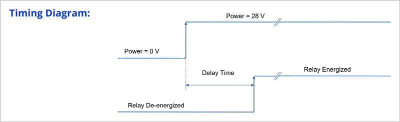
What is a Time Delay On Operate?
Time Delay On Operate is a two-terminal device with Integral Relay Sub-Assembly.
One terminal has the power (28 VDC) while the other terminal is the Return or Ground terminal.
When power is applied, the integral relay (output) energizes after lapse of the specified time.
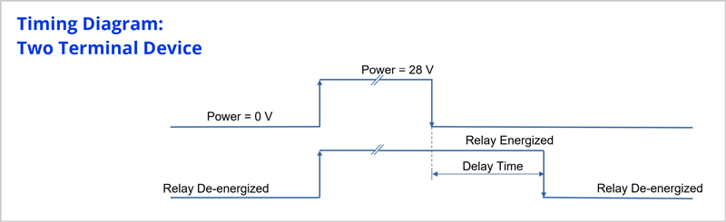
What is a Time Delay On Release?
Time Delay On Release is a two or three terminal device with Integral Relay Sub-Assembly.
• Power Terminal (28 VDC )
• Control Terminal
• Return or Ground Terminal
In the two terminal version, sometimes called “true time delay”, when power is applied the integral relay immediately energizes and stays energized. Subsequently when the power is removed (i.e. released), the integral relay de-energizes after lapse of the specified time.
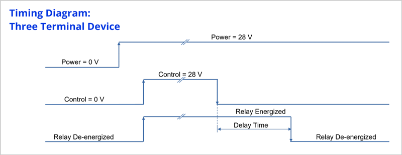
What is a Time Delay On Release? Cont’d
In the three terminal version when power is applied the integral relay stays de-energized. When power is applied to the control terminal, the relay energizes and stays energized. Subsequently when control power is removed (i.e. released) the integral relay de-energizes after lapse of the specified time.
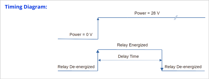
What is an Interval Timer?
An Interval Timer is a two-terminal device with Integral Relay Sub-Assembly. One terminal has the power (28 VDC) while the other terminal is the Return or Ground terminal.
When power is applied, the integral relay immediately energizes and stays energized until lapse of the specified time.
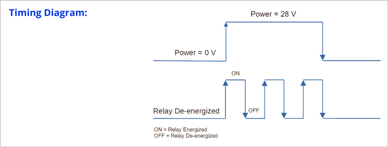
What is a Repeat Cycle Timer or Flasher?
Repeat Cycle Timer or Flasher is a two-terminal device Solid State output and Integral Relay Sub-Assembly.
One terminal has the power (28 VDC) while the other terminal is the Return or Ground terminal.
When power is applied, the integral relay energizes for the specified ON time then de-energizes for a certain OFF time and keeps repeating (i.e. flashing) this pattern for as long as power is applied.
How do you calculate the Time Delay in TDH families?
How to calculate the amount of time delay (-XXXX)
• -XXX: used to define the specific time delay
• X: number of zeros to follow the first 3 digits
Total delay in in milliseconds.
E.g. 2502 🡪 25000 msec 🡪 25 seconds
5000 🡪 500 msec 🡪 0.5 seconds
*To convert msec to seconds, divide by 1,000.
**If the fourth digit is 0, no zero is added after the first 3 digits.
Why am I measuring a different coil resistance than what is specified on the data sheet?
If you have a relay with back EMF suppression, measuring the resistance across the coil terminal pins is the equivalent resistance of the coil as well as the diode network for the back EMF suppression.
To find out the coil resistance for a relay with back EMF suppression, you need to use the voltage drop across the terminal and the measured current, then use Ohm’s law to calculate the coil resistance.
Where can I find the resistance of relay contacts?
Leach qualifies their relays to MIL-PRF standards and as such, it measures the contact voltage and current.
The contact resistor is not measured and is not part of the Product Control Drawing (PCD). You can use the voltage and current of the contacts with Ohm’s law to calculated the contact resistance.
I require PIND testing. Does Leach have the capability to perform this test?
Leach has the capability to perform PIND testing on all their relays.
PIND testing is not performed on Leach COTS and MIL-SPEC relays as it is not part of their requirements.
PIND testing is performed on 100% of Leach’s High Reliability and Space Rated relays. Leach designator for these parts is -254X, where X is the assurance level of the part.
What is the difference between COTS, MIL-Spec, Hi-Rel/Space COTS, and EEE-INST-002 class 1 relays?
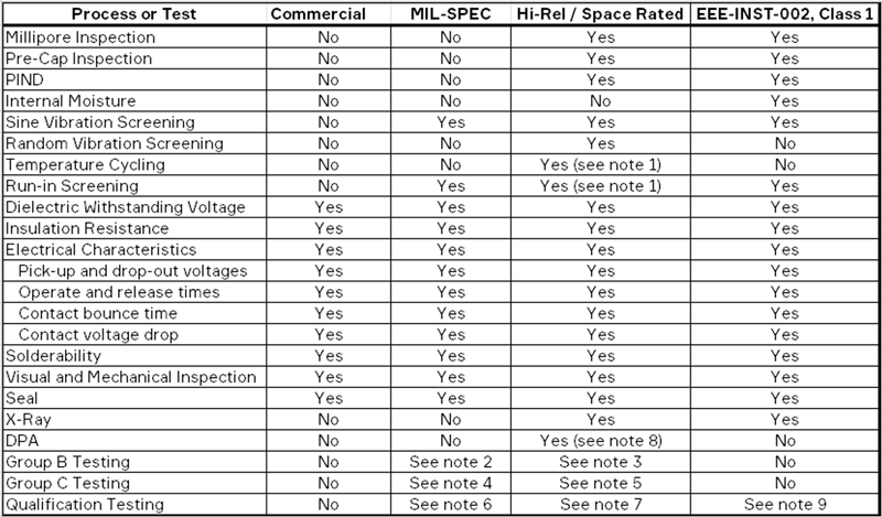
Note 1- Leach Space COTS relays receive five thermal cycles with run-in screening conducted on the fifth cycle.
Note 2 – Group B performed as part of annual QPL maintenance testing, on samples randomly pulled from production,
and is not lot specific.
Note 3 – Lot specific Group B is an option for Leach Space rated relay products (per Leach 500-1124-000-000 ATP
requirements), as specified by a customer SCD.
Note 4 – Group C is performed as part of annual QPL maintenance testing, on samples randomly pulled from
production, and is not lot specific.
Note 5 – Lot specific Group C is an option for Leach Space and Hi-Rel rated relay products as specified by a customer
SCD.
Note 6 – Full Qualification testing is performed once for the initial product qualification and is basically repeated every
three years based on quarterly Group B and C QPL maintenance testing.
Note 7 – Lot specific full Qualification is an option for Leach Space rated products (per Leach 500-1124-000-000 ATP
requirements), or as specified by the customer’s SCD.
Note 8 – The DPA performed per Leach 500-1124-000-000 ATP is based on MIL-STD-1580, however only includes internal visual and mechanical inspection. The customer has the option to send samples from the lot to an outside lab for a full DPA per MIL-STD-1580.
Note 9 – Full Qualification per the EEE-INST-002 specification requires 22 samples.
Note 10 – Leach 500-1124-000-000 requires a 15% PDA.
Note 11 – EE-INST-002 class 1 requires a 5% PDA.
What is the initial contact position of a latching relay?
Relays are shipped from the factory in the contact position shown on the schematic as the last energized position.
Would a demonstrated failure rate of 0.001% per 10 000 operations (one failure per billion operations) at the 90% confidence level be a reasonable failure rate to expect from a Hi-Rel relay?
No. A 0.01% per 10,000 operations failure rate at the 90% confidence level is considered to be about the lowest failure rate possible with the present state of the art. As a point of information, 23,100 relays, rated for 100 000 operations each, would have to be tested with no failures in order to demonstrate the 0.001% failure rate. It is very unlikely that a relay manufacturer would test and destroy many relays just to demonstrate a failure rate. Most likely, the accepted method was not used to calculate the relay failure rate.
What is the difference between a relay, a circuit breaker, and a switch?
By definition :
RELAY : An electromagnetic device for remote or automatic control that is actuated by variations in conditions of an electric circuit and wich, in turn, operates other devices (such as switches) in the same or a different circuit.
CIRCUIT BREAKER : A switch that automatically interrupts an electric circuit under an infrequent abnormal condition; e.g, a fault condition such as an overload or rupture of either high voltage or high current or both.
SWITCH : A device for making breaking or changing the connections in an electrical circuit. Usually mechanical and operated by hand.
Why can’t a power contactor switch low current?
The first question to answer is how low is the low current? Is the contact to be used for dry switching or to switch low level current?
Power contactors can switch low current, however, for switching low level currents or dry switching, there is no need for a heavy-duty contactor.
Power contactors have a tendency to falter or become intermittent when switching current of one ampere or less.
Under normal conditions, for low level current switching, a relay should be used.
Why do we have 3-phase ratings available?
For larger loads where higher current demand is required, 3-phase are more efficient. With 3-phase, a larger voltage (phase to phase) is available.
Why is relay reliability expressed in MCBF rather than MTBF like other electronic components?
Relay fallures are primarily due to functional operation (cycling) rather than the amount of time accumulated while operating. A relay manufacturer can not anticipate the number of cycles per hour the relay will be operated when installed in equipment. If the MTBF is required, the relay user can convert MCBF into MTBF by dividing the cycling rate (operations per hour) into the MCBF.
When a relay has demonstrated a given failure rate, is the failure rate applicable for all rated load conditions?
No. In order for a failure rate to be significant, the test conditions and the failure criteria must be stated, Without including these important factors, a failure rate is meaningless.
What is the effect on rellability by using relays in series to reduce high current arcs?
First of all, operate and release times of identical relays are not always the same therefore, the last relay to “make” and the first relay to “break” are the only contacts which would see the high current arc. Second, relays should never be used in series since the total reliability is reduced by the following relationship.
Total Reliability = R x R, where R is the reliablity of each unit.
What is the difference between resistive, Inductive, motor, and lamp loads?
We must express the load as a contact rating, which is the electrical load-handling capability of relay contacts under specified conditions and for a prescribed number of operations or life cycles.
RESISTIVE LOAD : A resistive load usually consists of some sort of resistance in the circuit: e.g. heaters, resistors, etc.
INDUCTIVE LOAD : An inductive load consists of a load created by a wire wound coil, such as in a relay or solenoid, a transformer, or any load which uses a winding over a magnetic iron core. Breaking an inductive load is usually more severe than breaking a resistive load and will generally produce heavy arcing.
MOTOR LOAD : A motor load can be referred to as a rotating inductive load, generally with a high inrush of six times the normal load. The breaking of the load is the same as a resistive load.
LAMP LOAD : There are many types of lamp loads such as tungsten filament, fluorescent, mercury-vapor, and other exotic gas lamps. The loads we normally concern ourselves with are tungsten filament. Tungsten filament lamps, when first turned on, will draw an inrush current of 10-15 times of the steady-state current. The inrush is similar to a motor load inrush and is caused by the cold filament in the lamp. After the lamp filament has heated up, the current will drop to its normal level. Most tungsten filament lamp load ratings are 20% of a resistive load.
What is a latch relay, and where is it used?
Latch relays are usually 2-coils, 2-position relays. The coil activation of one coil will transfer the armature and contacts to the other position. Conversely, activation of the other coil will transfer the armature and contacts back to its original position. The purpose of a latching relay is to conserve energy by pulsing the coil with a short pulse and removing the power once the relay has transferred. The latch relay lends itself easily to space applications because of minimal power drain on batteries.
What does normally open, normally closed mean?
The word “normally” refers to deenergized condition of the relay (no power on coil).
The second words “open” and “closed” refer to the position of the contacts at the deenergized condition.
Is there more than one method used to calculate relay reliability fallure rates?
Yes. There are several methods used to calculate relay failure rates. The accepted method and three other methods that are sometimes used to enhance a particular failure rate are shown below:
ACCEPTED
Method : Terminate testing with a failure, and one operation is one coil energized and de-energized cycle.
Total Operations : 10,000,000
Failures : 6
Failure Rate* : 0.600
SOMETIMES USED
Method : Terminate testing without a failure, and one operation is one coil energized and de-energized cycle.
Total Operations : 10,000,000
Failures : 5
Failure Rate* : 0.500
Method : Terminate testing with a failure: one operation is a contact make/break per coil energized and de-energized cycle.
Total Operations : 80,000,000
Failures : 6
Failure Rate* : 0.075
Method : Terminate testing with a failure: one operation is a contact make/break per coil energized and de-energized cycle.
Total Operations : 80,000,000
Failures : 5
Failure Rate* : 0.063
*Failure rate is expressed in % per 10,000 operations.
Is MCBF a guaranteed period of failure-free service?
No. An MCBF is derived from live testing a large number of relays for their minimum rated life. The number of failures that occur during the testing are then divided into the total number of completed operations.
How does a relay work?
A relay is an electromagnetic device, within wich an electro magnet (sometimes called a motor) is fixtured to cause controlled movement either by magnetic attraction or magnetic repulsion. Other hardware attached to the moving magnetic portion of the motor such as relay contacts will cause switching of electrical circuits.
Explain center-off relays. When and where should they be used?
A center-off relay such as a HC or ZC contactor (relay) has its contacts in a null position, when deenergized. This means that the moving contact is not making contact with either stationary contact. The relay contactor has two coils, and each coil operates the moving contact to one or the other stationary contact position.
Center-off relays/contactors can do the following:
• Transfer a power source to two different positions
• Transfer one circuit to another circuit
Do Initial screening tests have any effect on the rellability of relays during the use life?
Yes. Screening tests detect those failures, which would otherwise occur during the early life of a relay. This is why it is important to know what screening tests are performed by the manufacturer.
Can a 99% reliability for a particular mission time be achieved when a relay is only capable of 90%?
Yes, Two relays with a 90% reliability can be used in parallel to achieve a combined reliability of 99%.
Are there any latent costs that should be considered in the procurement of relays?
Yes. Although relays appear relatively inexpensive when compared to the cost of an entire system, there is one big cost factor that is almost always overlooked. That is the cost of a field failure caused by a relay malfunction.
There is a simple method to determine the “add-on” failure cost of a relay. By dividing the minimum rated life cycles of a relay into its demonstrated MOBE, you can determine how many relays will be used before a failure will occur. Now, by amortizing the estimated cost of a field failure over the number of relays to be used, you will know the “add-on” cost per relay.
Formula:
Add on Cost/Relay = Cost of Field Failure ÷ MCBF ÷ Min.Rated Life
Example:
$500 ÷ 1,000,000 ÷ 100,000 = $50
What is the difference between 50, 60, and 400 Hz?
Most AC (alternating current) relays operate on standard frequencies and voltages.
50 Hz FREQUENCY : This is a standard alternating current frequency used mostly in Europe, Africa, Australia and Asia. Voltages commonly used with this frequency are: 115VAC 1-Phase, 115/220 3-Phase, 220VAC 1-Phase, 220/440 3-Phase.
60 Hz FREQUENCY : This is a standard frequency used primarily in the USA and Canada, but it is also used in many other countries. The typical voltages used in households and industries are 115VAC 1-Phase, 115/200 3-Phase, 220/400 VAC. In some instances heavy industry will use 440/660VAC 3-Phase.
400Hz FREQUENCY : This is a standard frequency used in most commercial/military aircraft. It is also used on Navy aircraft carriers, but primarily to service aircraft. Most aircraft utilize the 115/208 VAC 400 Hz WYE system, except some newer aircraft, which use 230/400 VAC 400 Hz because of its lighter weight generator system. The 400 Hz frequency is used in aircraft systems primarily because the generators are much lighter in weight. 50/60 Hz frequencies are used because that was the chosen frequency by the federal government years ago, and no one has upgraded the frequency because of the associated cost.
How does using relays in series to reduce high current arcs affect reliability?
The operate and release times of identical relays are not always the same therefore, the last relay to “make” and the first relay to “break” are the only contacts which would see the high current arc. It is not recommended to use relays in series since the total reliability is reduced by the following relationship.
Total Reliability = R x R, where R is the reliability of each unit.